
by
Richard D. Moats
Overview:
The Salisbury brothers authored a paper in 1862 describing several sites in Ohio. One of the sites they described was an “Ancient Symbolic Earth Works” in Northern Perry County. The paper included a narrative and plot map of a hill top earthwork and three associated features. They were precise in their linear measurements, angles of intersection, and vertical heights. They also described five structures with flat tops which they termed “platforms” and another as an open “C” shaped structure (Salisbury and Salisbury 1862). Warren K. Moorehead published a short article describing the site and named it “Frank Yost’s Mounds” after the landowner. The only significant additional information he provided was finding ash in what he termed the “bird effigy” located inside a large circular enclosure. He did not address other large geometric features suggesting some destruction of the site had occurred (Moorehead 1896). Moorehead’s report did not contain the aggregate detail or descriptions of the entire structure as described in the Salisbury document. This indicates that erosion and intentional agricultural destruction began in the latter half of the 19th century. Until recently, the large circle with the internal crescent and the small mound nearby are the only features known to exist into modern times. It is apparent the site had been a very complex Hopewell earthwork with features unlike any other known Hopewell site but has been nearly completely destroyed.
This paper encompasses the rediscovery of lost features, and digital reconstruction of the site. I will show how the site integrates distant terrestrial features and offer my research into the purpose of this three dimensional geometric structure. I will demonstrate how construction and spatial orientation of the structure provided alignments with celestial body rise and set points. I will describe the visual illusions created by solar and lunar rises and settings in relation to the earthwork and a long distance feature.
Plot Map Construction:
The center of the site, 33Pe5, known today as the “Yost Works”, is located on a hill top at 35°54’02”N x 82°20’31”W in Northern Perry County, Ohio. To the south of these coordinates is a large circular enclosure and a small nearby mound both covered by trees and brush. Inside the enclosure on the south interior perimeter is an earthen crescent with a central “bulge” which, when viewed from above resembles an effigy of a spread wing bird. Until recently, these are the only features of the geometric structure known to have survived. The orientation of the site described by the Salisburys is based on magnetic compass readings and the angle of declination for this location in 1862 is not known. Construction of an accurate site plot map began with entering the linear measurements generated by the Salisbury’s into a Computer Aided Design Program, (CAD). Scale and orientation needed to be verified before an accurate reconstruction could be completed. Dr. William F. Romain, a specialist in Light Detection And Ranging, LiDAR, provided aerial images of the site. By using LiDAR in bare earth mode, foliage is filtered out and subtle terrain elevations are imaged (2008a, 2008b. Romain and Burks).
Analysis of the LiDAR image revealed the large circle, nearby mound, and remnants of the original structure. The additional remnants of the earthwork delineated were the ends of two causeways, and portions of the causeway walls in the tilled field (figure 1).

LiDAR image revealing earthwork features. Image by W. F. Romain, Analysis, R. Moats
The CAD image was then sized to register with the LiDAR imagery data points resulting in an accurate; two dimensional scaled map primarily based on the LiDAR data (figure 2).

Computer Aided Design, CAD, plot of site registered to align with the LiDAR data points. Image, R. Moats and D. Hill
Azimuths, midlines and sight lines were measured and constructed to complete the final site plot map (figure 3).

Completed site plot map. Image, R. Moats
This new site plot was then registered to an aerial image of the site made in 2012 (figure 4).

Site plot registered to 2012 aerial image. Plot, R. Moats, Aerial, Google Earth
It was then possible to use the Google Earth™ computer program to make linear measurements. This earthwork was very large having an aggregate size of 1054 feet by 1180 feet by 1015 feet.
Dr. Jarrod Burks performed Geophysical Surveys of the site using magnetic and electrical resistance technologies. The surveys did not add to the data base because of extensive destruction of the site and the placement of underground oil lines. The minimal data recovered only supported some of the known data.
Suppositions:
Without a carbon 14 date for the site and considering its advanced form and complexity, it is supposed that this site was constructed in the middle to late Hopewell cultural era. For this reason, a date of reference for all alignments of 250 AD was selected. A variation of ±500 years is not a significant factor given the tolerances in this research. Solar and lunar alignments are not significantly affected by time variations less than ±1000 years. Therefore, a reference date of 250 AD is well within the parameters for accurate testing.
The Salisbury’s described five features in the earthworks as “platforms”, P1, P2, P3, P4, and P6. These five platforms were the same height as the earthwork, four feet, with flat upper surfaces on which a person could stand but be confined to a specific location such as for precise sightline viewing. P5 is a “C” shaped enclosure with the interior at terrain level. These six features will be considered to be “observation platforms or view points” for celestial alignments (figure 2).
Site Reconstruction:
The Global Positioning System, GPS, was used to determine terrain elevations above mean sea level. It was then possible to render a three dimensional view of the geometric structure. This reveals the earthwork was built over the crest of a hill using the variations in terrain elevation to create six different observation locations and elevations. The structure is now viewed as a three dimensional structure having six different elevations for six observation locations and the center of the central circle at the highest terrain elevation. The earthwork height above terrain elevation is a uniform 4 feet with the exception of the south east wall which was two to three feet (figure 5).
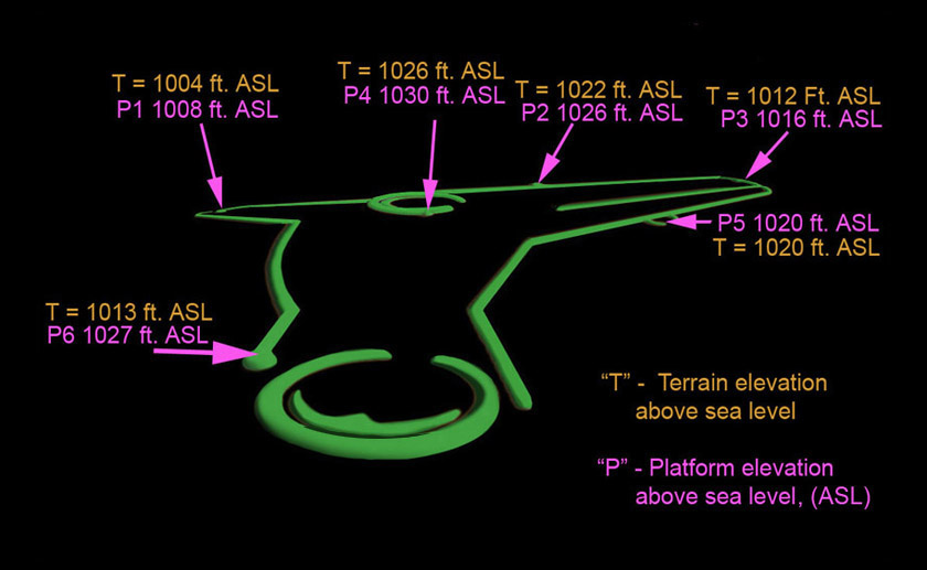
Three dimensional drawing of the earthwork showing terrain and platform elevations above sea level. Image, R. Moats
A wider view LiDAR image delineated three outlying features described by the Salisburys, the “North Mound”, “Pool”, and “T Mound”. The image is a 90° overhead composite view which eliminates linear distortion (figure 6).
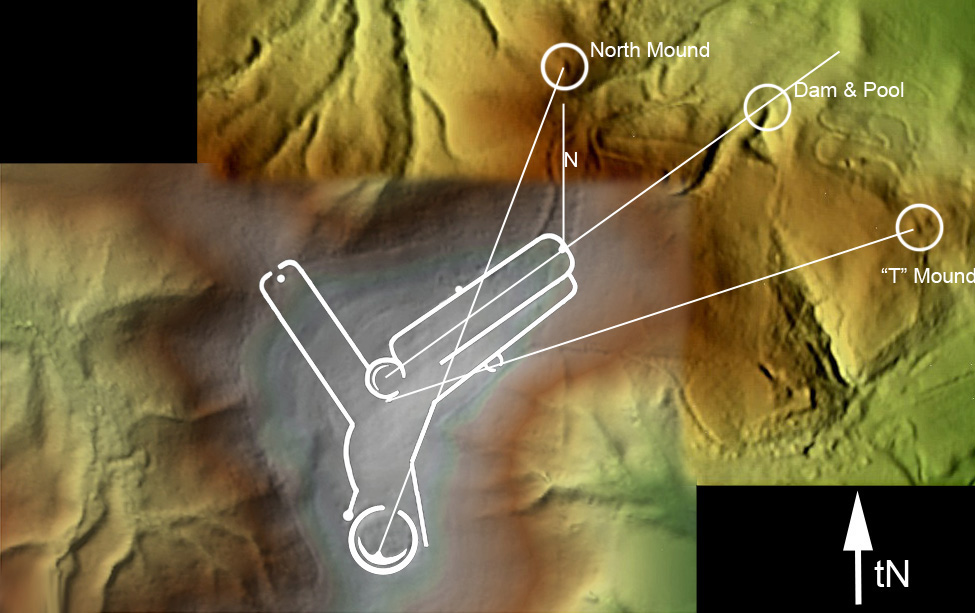
Mosaic LiDAR images showing the earthworks and outlying structures. LiDAR image W.F.Romain, Interpretation and overlays, R. Moats
The “North Mound”, (figure 7),
Highlighted “North Mound”. Image, R. Moats
is a 36 X 60 foot elliptical shaped mound oriented north/south through the long axis midline. The center of this mound is north of platform, P3.
A “Pool”, (figure 8),

Highlighted “Pool and Dam”. Image, R. Moats
formed by a low earthen dam holding water from a spring, lies on an azimuth of 58° ±2° from the center of the central circle. This azimuth is also the centerline axis of the north east causeway.
The “T Mound”, (figure 9),

Highlighted “T Mound”. Image, R. Moats
or as the Salisburys named it “Human Shaped Symbolic Mound”, sits east of platform P3. Its shape is not well discerned because of agricultural destruction. Also, a dirt bike track was built through the mound which destroyed more of the structure. Based on the description in the Salisbury text and current observations, the “T” shaped mound is oriented to the cardinal directions. The longest midline, 80 feet, is in line with an east/west axis and the cross midline, 36 feet, on a north/south axis with the top of the “T” being to the west.
Terrestrial Alignments:
The three outlying structures, the North Mound, Pool, and T Mound, are clearly associated with the large earthwork by their proximity and cardinal direction. The alignments suggest the three features at lower elevations were part of the geometric structure but without accurate dating it is unknown as to the sequence of building (figure 6).
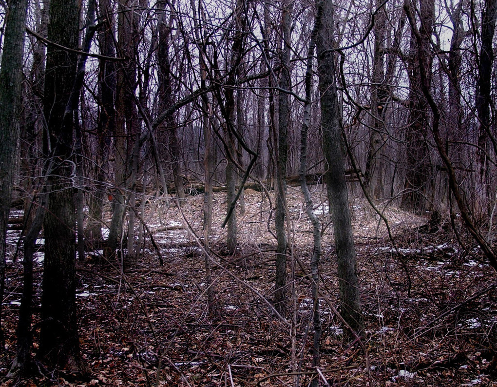
On azimuth 090° east ±.5° at a distance of 12,672 feet and a base horizon of less than +1º as viewed from the center of P6, there is a large earthen mound (figure 10).

The Roberts Mound, winter 2010. Image, R. Moats
This feature is known as the Roberts Mound. It was excavated in 1904 by W.K. Moorehead (1906). Before excavation, the height of the mound was 27 feet. The current height above ground level is 18 feet as it was left in1904. Moorehead found an abundance of ash and a partially cremated skeleton in association with an expanded center gorget inside the mound. This association is evidence for this mound being an Adena mound and therefore older than middle to late Hopewell earthworks. This east/west alignment is evidence for the intentional placement of observation mound P6 to align with the older Roberts Mound on an azimuth of 090°/270º (figure 11).

Plot showing alignment of P6 with the distant Roberts Mound. Image, R. Moats
Azimuth of 090º east is the midpoint between the solstice stand stills and represents the two equinox solar rise points at zero degrees horizon elevation; the vernal around March 21st and the autumnal around September 21st, both ±2 days. A study of terrain elevations minus obstructive trees indicates the Roberts Mound was completely visible from observation mound P6. At a height of 27 feet plus, the mound was prominently silhouetted against the eastern sky when viewed from P6.
Archaeoastronomy:
In order to search for archaeoastronomical alignments it was necessary to establish viewing points, sight lines, and horizon elevations. The viewpoints are supposed to be the “platforms” P1, 2, 3, 4, & 6 and the “C” shaped structure P5. The horizon elevations were calculated for an observer with a ground to eye height of 5.5 feet. The formula is inverse tan x = VD/HD where VD means vertical distance, HD means horizontal distance with VD = C-A where A is backsight location elevation +5.5 and C is foresight location elevation (figure 5).
The horizon rise or set points were tested in two computer planetarium programs, Winstar™ and Stellarium™. Calibrations were made for each observation location and elevation for the year 250 AD. These programs correct for Delta T, refraction, and precession.
The data used for this research is the best available to date. With the earthwork being largely destroyed, possible errors in linear measurements, translation, methods, and registration of the overlays, the margin for error in the alignments is estimated at ±1º for azimuths and ±.5º for elevations. Since the focus of the observer was on the illusions of rises and sets in relationship to the earthwork, the tolerances noted are well within acceptable limits.
Figure 12

Orientation plot showing alignments of the site. See Key 12. Image, R. Moats
shows the astronomical alignments of the site. These alignments are critical for celestial body rise and set points and understanding the mechanics of the Archaeoastronomy. Key 12 explains each alignment.
A. Az 058 degrees. North maximum of ecliptic plane rise.
B. Az 124 degrees at +3 degrees horizon elevation. South maximum of ecliptic plane rise.
C. Az 090 degrees east. Solar equinox rise at zero degrees elev.
D. Az 180 degrees south.
E. Az 238 degrees at +1 degree horizon elevation.
F. Az 270 degrees west. Solar equinox set at zero degrees elev.
True North and South Azimuth 360º/180º passes through the centers of the two circles.
The Central Circle was an open enclosure with an internal crescent. Its position was not only in the center of the geometric structure but was the highest in elevation of all other features.Being the center of the site, the central circle played a vital role in the many alignments and illusions. The diameter of the circle was 115 feet from top centers ± 1 foot. The angle of view from P1 to the top of the central circle is +3º. From the platform mound at the northwest end of the causeway, viewpoint “P1”, azimuths of 118° and 133° intersect with the perimeter of the circle and coincide with the minimum and maximum lunar south rise points at +3° horizon elevation. From platform P3, azimuths 229º and 244º, the minimum and maximum lunar south set points at +1º elevation, also intersect the perimeters of the central circle. This suggests the diameter of the central circle was determined by the southern lunar rise and set points and/or the positions of P1 and P3 in relationship to the central circle (figure 13).

Plot showing azimuths of the perimeters of the central circle. Image, R. Moats
It is only speculative as to the meaning of the internal crescent. When viewed from above it resembles an effigy of a crescent moon or a crescent formed by an eclipse of the moon or sun. Between the year 1AD and 300AD there were 77 partial and 84 total lunar eclipses visible from the site. In the same period, there were 181 partial solar eclipses. Eight of these were 90% to 99%. There were no total solar eclipses viewable from the site location in this time period. (2012. NASA)
Maximum north risings of the sun and moon were viewed from P4. When the sun rise occurred on Az 057.5º, upper limb tangent to 058.2º lower limb tangent, at zero degrees horizon elevation, it was the longest day of the year. This rise point for the sun is the Summer Solstice and is confirmed in the planetarium programs as the maximum northern intersection of the ecliptic plane and a zero degree elevation horizon at this location. The parallel walls and midline of the north east causeway align with azimuth 058º/238º. The illusion, as viewed from P4, was the sun rising in alignment with the south wall of the east causeway (figure 14).

Summer Solstice Sunrise from P4 in alignment with the south wall of the east Corridor. Image, R. Moats
If the viewpoint was from the center of the central circle, the sun appeared to rise over the middle of the end of the causeway and P3 (figure 15).

Summer Solstice Sunrise from the center of the central circle sighting down the midline of the east corridor. Image, R. Moats
The moon would frequently rise within the 10º view angle of the end of the causeway when viewed from the center of the central circle. On occasion, the rise point would be at Az 053º when viewed from P4. When rising at this maximum north rise point, once every 18.6 years, the moon rises over P3 at the middle end of the east causeway when viewed from P4 (figure 16).

The Northern Lunistice at maximum north rise viewed from P4. Image, R. Moats
This azimuth is the north maximum rise point and thestandstill of thelunar orbit to the north, the North Lunistice.
On nights of mid-summer, the ecliptic plane and the lunar cycle frequently placed the moon over the large circle at its lowest possible elevation as low as +20º when viewed from P2; a dramatic difference from its highest orbital path of nearly straight overhead. Ash was reported at the central bulge of the internal crescent of the large circle by Moorehead in 1896. A fire at this location in the circle could send smoke across the lunar disk. The moon was never lower in the south over the large circle than at +20 degrees elevation (figure 17).

The moon over the large circle when at its lowest southern elevation of 20 degrees as viewed from P4. Smoke from a fire intersects with the moon.
Image, R. Moats
Maximum South Risings of the sun and moon were viewed from P1. The intersection of the ecliptic plane at maximum south at a zero degree horizon is Az121º. When the sun rises at the maximum south rise point it is the Winter Solstice. With a horizon elevation of +3º the maximum south rise point becomes Az 124º, the top center of the central circle when viewed from P1. When viewed from P1 and sighting along Azimuth 124º at a +3º horizon elevation, the sun appeared to rise out of the central circle on Winter Solstice morning (figure 18).

The sun rises out of the central circle on Winter Solstice morning when viewed from P1. Image, R. Moats
With a viewing angle of 15º between the perimeters of the central circle when viewed from P1, the moon on many occasions during the year appeared to rise out of the circle between Az 118º and Az133º. The southern most rise point, the South Lunistice, placed the moon rise at 133º at +3º horizon elevation. The south Lunistice moon therefore appeared to rise from the right edge of the central circle when viewed from P1.
On Winter Solstice mid-day, the ecliptic plane is at its lowest elevation on the southern horizon at +26.5º. On this shortest day of the year, when the sight line was along Az 180º at -1º horizon elevation from P4, the sun was viewed to be directly above the large circle. This is the precise moment of the winter solstice at this location, the meridian transit of the sun (figure 19).

Sighting along azimuth 180º from P4, the sun is directly over the large circle at the moment of meridian transit, the Winter Solstice. Image R. Moats
The function of P2 is not known at this time. It appears as if the earthwork was truncated on the west end of the southeast wall so a viewer standing on P2 could see over the near terrain and into the large circle on a zero degree horizon elevation. This sight line from P2 is through the center of the opening and in alignment with the central “bulge” in the internal crescent on azimuth 197º (figure 20).

Sighting from P2 on azimuth 197º, the sun is suspended above the circle at midday of the Winter Solstice at 26º. Smoke from a fire covers the sun. Image, R. Moats
Maximum South Settings were viewed from P3 and sighting along Az 238º. This sight line passes through the center of the central circle at a horizon elevation of +1º at the top center of the central circle. The view angle for the perimeters of the circle is a narrow 7.5 degrees; ½ the angle when viewed from P1. From the perspective of P3, the sun appeared to set into the center of the central circle on winter solstice evening on Az 238º at +1º elevation, lower limb tangent contact (figure 21).

The sun setting into the central circle on Winter Solstice evening when viewed from P3. Image, R. Moats
The maximum and minimum south set points of the lunar cycle are between AZ 229º and 244º respectively. From P3 and sighting along the midline of the causeway on Az 238º, the moon was also frequently observed to set into the central circle.
Equinox Rises at Az 090º were viewed from P6. When the sun rises at this azimuth it is termed an equinox. There are two equinox sunrises in a year, the vernal on March 21st and the autumnal on September 21st, both ± 2 days. When viewed from P6, on or close to these dates, the sun appeared to rise behind the distant Roberts Mound 12,672 feet across the valley on the far horizon. This created a spectacular illusion. The Roberts Mound was silhouetted against the solar disk at the midpoint in the solar cycle. The placement of P6 is within ±.5º of azimuth 090º/270º which was critical for equinox alignments (figure 22).

The illusion caused by the sun rising behind the Roberts Mound close to an equinox. Image, R. Moats
Lunar rises also provided a similar illusion (figure 23).
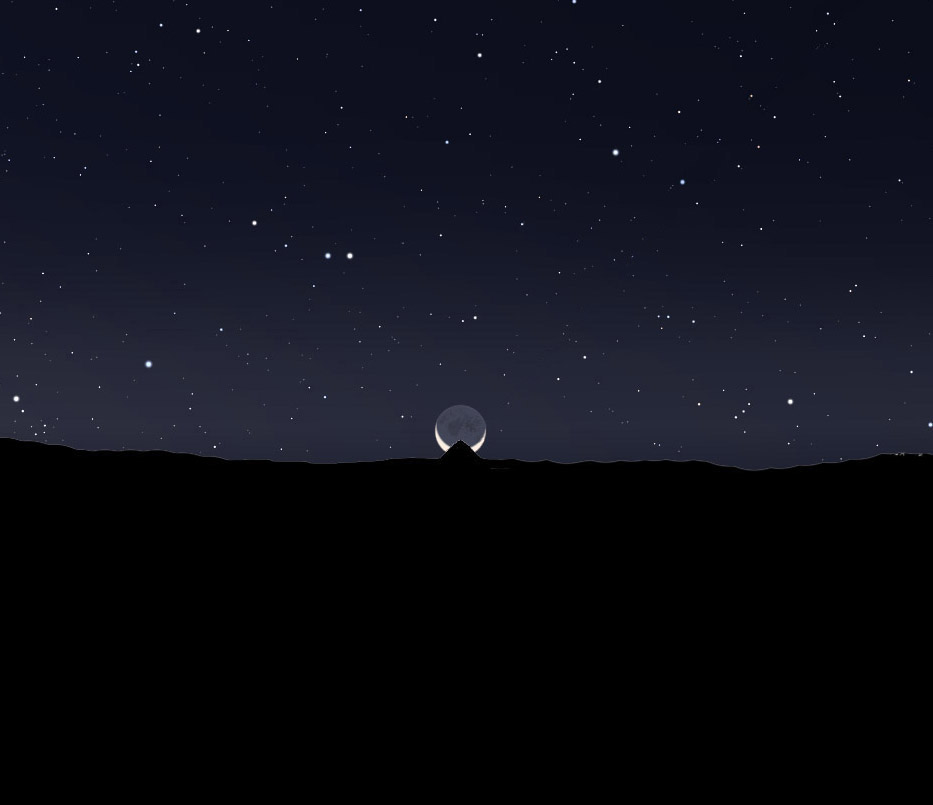
A crescent moon rising behind Roberts Mound as viewed from P6. Image, R. Moats
Because of the required timing, and the perturbations of the lunar orbit, a lunar alignment behind Roberts mound may only occur only one or two times per year. Given these constrains it appears that the illusion of a crescent moon rising behind the Roberts Mound was replicated in the internal structure of the large mound. This does not negate the possibility the analog of the illusion is that of the solar disk. It could be an analog for both (figure 24).

The large circle is an analog for the illusion of the sun or moon rising behind the Roberts Mound. Insert is a LiDAR image of the circle. Image, R. Moats. LiDAR image W.F.Romain
Equinox Sets occur on or close to Az 270º. Feature P5, the “C” shaped enclosure on the south wall, is on Az 090º/270º in relation to the central circle. A viewer standing in this enclosure and sighting west along Az 270º would see the top of the central circle on the near horizon at an elevation of +1º. The angle of view between the perimeters of the central circle from P5 is 20º. On the evening of an equinox, the sun sets at Az 270º. The illusion from P5 was the sun setting into the central circle.
The ecliptic plane crosses over Az 270º two times in a twenty four hour period. When the ecliptic plane intersected azimuth 270º during darkness, the moon was oftenviewed to set into the central circle when the observer was inside P5 (figure 25).

25 Illustration of the sun or moon setting into the central circle around the times of equinox when viewed from P5. R. Moats
The ecliptic plane angle is 17º right of vertical when viewed on azimuth 090º at autumnal equinox sunrise (figure 26).

A screen shot showing the ecliptic and equatorial planes at the time of autumnal equinox in the year 250. Image, Winstars™
This angle of the ecliptic plane at 17º from vertical occurs again in the evening of the vernal equinox (figure 27).

A screen shot of the ecliptic and equatorial planes at the time of vernal equinox in the evening of the year 250. Image, Winstars™
These are the times when the sun and moon could rise behind Roberts Mound when viewed from P6. The angle of the centerline of the large circle opening from true north is also 17º. This centerline coincides with the sightline from P2 into the central circle (figure 28).

The site plot map is overlaid onto a screen shot showing the coincidence of the P2 sightline of 17º with the ecliptic plane at equinox times. Image, Winstars™ and R. Moats
Planets, Stars, and Constellations could have been observed and monitored similar to the risings and settings as the sun and moon. The visible planet orbits are on or close to the ecliptic plane. The rise and set points for the planets could therefore be nearly the same as for the sun and moon. The planets have longer periods than the sun or moon and would therefore be observed over a longer period, perhaps months or even years as in the case of Mars and Venus (table 1).
Synodic Periods
Planet Period Earth Days
Jupiter 1.092 398.58
Mars 2.135 774.75
Mercury 0.317 115.70
Saturn 1.035 377.77
Venus 1.599 583.63
Any planet, star, or constellation alignment with the earthworks is likely due to chance but cannot be confirmed or ruled out.
Summary:
Considering the intricate construction, precise orientation, and the three dimensional properties which were necessary to achieve the alignments I have demonstrated, it is my conclusion that this site was a unique Hopewell Celestial Observatory. The site was used to observe the yearly and long period cycles of celestial objects. The illusion of the sun, moon rising and setting was the purpose for building the structure.
The builders, operators, and observers obviously attached great significance to objects moving in the sky above. Construction of this earthwork required time, people, and knowledge. The time necessary for construction required multiple people following the directions of one or a small group of individuals who had knowledge regarding the cycles of the heavenly bodies. The key knowledge was determining the minimum and maximum north and south intersections of the ecliptic plane with the horizon in both the east and west. This could have been determined by long term observations of the solar and lunar rise and set points. The orientation of the opening of the large circle and the position of P2 however suggests the builders may have had some comprehension of the ecliptic plane. If the effigy inside the central circle is that of an eclipse, then this may further support an understanding of the ecliptic plane.
The motivation required for so many to work toward a common goal had to be rooted in a common belief system. The belief system is manifest in the structure. The significance of each observation and illusion related to the belief system. The predictability and reoccurrence of events from year to year or over long periods likely validated the belief system and afforded assurance of a continuation of the cycle.Interpretation of the belief system must then be based on what we can interpret from the visual illusions seen by the observers.
The building and operation of the earthwork had a much more complex function than of a seasonal time keeping devise. Seasonal changes in the environment such as seen in foliage, animals, temperatures, and the length of days, all were undoubtedly used to predict the coming seasons. A complex earthwork was not necessary for the people of the time to predict seasonal cycles.
The illusion of the sun and/or moon rising behind the Roberts mound obviously played an important role in the construction and operation of the site. The large circle with its internal effigy and the precise placement of P6 on azimuth 090º/270º suggests there was an understanding of the midpoint between the solar and lunar standstills. The illusions involving a burial mound suggests something related to burial or after-life beliefs.
The focus on the Winter Solstice seems to outweigh other celestial cycle events. Not only is the winter solstice sunrise and sunset observed, but also the midday winter solstice sun over the large circle. These illusions centered around the winter solstice strongly suggest winter solstice time played a major role in the belief system.
The Hopewell had a shamanistic view of their world (Eliade, 1964; Furst, 1976; Romain 2009). In this view, the cosmos is comprised of three levels, the Upperworld, their Earth, and the Lowerworld. In this cosmology, the Upperworld contains the sun, moon, and stars as well as birds. One of these birds, which is part of some modern Native American belief systems, is the Thunderbird. The similarity of the effigy in the large circle to that of a winged bird, created after the illusion of the sun and/or moon rising behind Roberts mound, may relate to this Upperworld creature.
The earth is often viewed as circular containing all the attributes of physical reality. The Lowerworld is under the earth and contains water, all the aquatic creatures including snakes, alligators, and mythical characters. These three levels are connected by a vertical axis called an “axis mundi” or “pathway”.
The vertical axis mundi can be a column of smoke (Romain, 2009). With this pathway connecting to the upper world, communications in the form of prayers and supplications for continuation of the life cycle could have been offered. The visual illusion of the smoke carrying their requests to elements in the Upperworld may have been an integral function of this complex. Evidence of fires reported by Moorehead in the large circle suggests this hypothesis may apply to this site.
Regardless of their beliefs, when celestial events recurred as hoped, and/or predicted, their perception of success may have been based in their own efforts. If prayers and supplications to ancestral spirits or a higher being were offered for continuation of the life cycle, renewal and continuation likely proved to them their efforts were successful and their requests had been heard and honored. Recurrence validated their belief system.
The Hopewell may have viewed the cosmos as an accessible realm. With the primary focus of activities centered on the winter solstice, the most threatening time in the solar cycle in regards to survival, they may have believed they could influence the sun and moon to raise high in the sky again and continue the life cycle.
The Hopewell at this venue built this three dimensional earthwork high on a hill top, close to the sky; closer to the Upperworld. Their motivations may have involved worship, burial ritual, life cycle rebirth, or maybe they were simply trying to understand the cosmos. Regardless of their motivations, we must stand in great respect for these people we call the Hopewell.
Acknowledgements:
I dedicate this work in memory to my dear friend William Cleaves. He helped me greatly with measurements and locating features. He passed unexpectedly. Dr. Romain provided the LiDAR images and reviewed earlier drafts of this manuscript. I am solely responsible for the content, any errors, and interpretations offered herein. Thank you Dr. Bill. Dr. Jarrod Burks provided the copy of the Salisbury document. He also spent three days of hard work doing geophysical surveys at the site for only food as payment. Thank you Dr. Jarrod. Thanks to Mr. Daniel C. Hill, Civil Engineering Draftsman, for CAD assistance. And special thanks to my wife Hazel for her patience and understanding during this four year project. “Behind every man……”
Final Note:
When Europeans began to move into the landscape of the Ohio Valley, earthen circles with internal crescents were in great abundance. In the words of Dr. Romain, “I challenge anyone to find one of these today”. “The large circle with the internal crescent effigy at the Yost Works is likely the last of its kind”. Efforts are being made to put this entire site into Archaeological Conservancy to legally protect it from any further destruction.
Feel free to contact Mr. Moats: rmoatsarch@gmail.com
References Cited:
Eliade, Mircea
1964. Shamanism: Archaic Techniques of Ecstasy. Pantheon Books.
Furst, Peter
1976. Shamanistic Survivals in Mesoamerican Religion. Actas del XLI Congreso Internacional de Americanistas
Google Earth™
2012 Earth viewing and measuring program: Google Corporation, freeware
Romain, William F., and Jarrod Burks
2008a LiDAR Imaging of the Great Hopewell Road. Current Research in Ohio Archaeology 2008.
2008b LiDAR Assessment of the Newark Earthworks. Current Research in Ohio Archaeology 2008.
Romain, William F., PhD.
2009. Shamans Of The Lost World, Page 85, Altamira press.
Moorehead, Warren K.
1896. Frank Yost’s Mounds, Ohio Archaeological and Historical Quarterly, Vol. 5, Pg. 17. Ohio Historical Journal, season 1896, Vol.5, Page 165.
1906. The so-called “gorgets”, Peabody and Moorehead, Andover Press, Page 89
National Aeronautics and Space Administration, NASA,
Eclipse Data web site, www.nasa.gov
Planetarium Programs:
Winstars™, www.winstars.net and Stellarium™, www.stellarium.com , freeware.
Salisbury, James H., MD and Charles B. Salisbury
1862. Ancient Monuments and Inscription of and near the Summit Between the Head Waters of the Hocking and Licking Rivers, Ohio, Page 23, Ancient Symbolic Earth Works. Transcript from Dr. Jarrod Burks: Original on file American Antiquarian Society, Worchester, Mass.